

11/10/2010
10/27/2010
Unified Thread class defined
The unified thread classification which includes the UNF, UNC systems is sectioned out into thread classes used for thread form tolerances. Here is a great description from Wikidpedia
A classification system exists for ease of manufacture and interchangeability of fabricated threaded items. Most (but certainly not all) threaded items are made to a classification standard called the Unified Screw Thread Standard Series. This system is analogous to the fits used with assembled parts.
Classes 1A, 2A, 3A apply to external threads; Classes 1B, 2B, 3B apply to internal threads.
Class 1 threads are loosely fitting threads intended for ease of assembly or use in a dirty environment.
Class 2 threads are the most common. They are designed to maximize strength considering typical machine shop capability and machine practice.
Class 3 threads are used for closer tolerances.
Thread class refers to the acceptable range of pitch diameter for any given thread. The pitch diameter is indicated as Dp in the figure shown above. There are several methods that are used to measure the pitch diameter. The most common method used in production is by way of a GO-NO-GO gage.
Per ASME Y14.6 -2007 Para 3.2.2, the thread definition and class should be expressed as such:
ex: 5/8-11 UNF-2A
10/26/2010
Threads as datums
In ASME Y14.5 2009 it's stated that it's okay to use threads as datums.


This is telling us to select the feature axis "B" which is a calculated result of the thread pitch.
If it's the intension use the major diameter as our datum simulator we need to communicate this next to the datum as such...

Now the reader knows for sure that it's okay to use the outer most surface of the threads as a datum regardless of feature size (RFS).
10/25/2010
Dimension Origin
Per ASME 2004, then later adopted in 2009, The Dimension Origin symbol is a virtually unknown in the drafting world simply do to the fact that a datum does the same thing, but with added versatility. This symbol just signifies from what surface the dimension should start.


Refer to the ASME Y14.5 2009 Fig 3-11 and para 3.3.17.
In Solidworks, All you need to do is right click on the leader display point on the dimension it's self, then select the circle from the drop down list....easy :)

Point Selection.

Drop down menu will appear.

Finished result...just like the ASME guide states.
10/21/2010
A free PDM....What??
I have been looking for a PDM that I can install on my home system just to keep myself organized. PDM Enterprise, Team Center and others....just a cost a stupid amount of money for my purposes.

I came across an affordable (free) PDM system that claims to be fit for industry. I have not put it to the industrial test yet, but I have used it for my home data and it appears to hold up :) Check it out for yourself!
http://www.gopdm.com/ from Fawcett Design Inc.

10/20/2010
Balloons (Add to Stack) in Solidworks.
So, its common drafting practice to add balloons to your drawing for labeling individual parts in the BOM. What gets a little tricky is how to label parts like adhesives, tapes, and thread lockers that have no model. Enter the "Add to Stack" command!


In this example we have an STI threaded hole that requires a the thread insert and some kind of thread locker. Its simple to define a local assembly process for this.
1. In the Drawing, add the balloon as usual. Flag note 6 next to the STI (item 3) points us to an assembly note on page one.

2. Right click on item 3 and choose "Add to Stack" from the drop down menu. We do have the option of choosing the direction of where the balloon stack will go.


3. In order to make the balloon stay, we need to select a part for it to reference. Just choose to main part (in this case, item one) depending on how your defaults are set up. You should have two items ones. My balloon selection is set to "Item Number".

4. Now we need to edit the second item number one to reflect what's actually on the BOM. This needs needs to be edited manually. In this case our thread locker is item 2 with a quantity of "AR" (As Required). Click on the balloon and select "Text" from the Balloon text entry on the Balloon Settings menu.

5. All that's left is define the quantity of "AR" next to the balloon..which of course is optional. Your BOM should match up with your balloons.

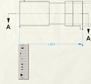
Arc-Length Measurements in Solidworks
While sketching in Solidworks, we may want to actually specify the length of the arc instead of point to point length, or arc center to end point. here is a great little method that I think is under used...and not very well known.


The AMSE, ISO symbol is: 

1. Sketch an arc of any verity..just not a closed circle.

2. open you smart dimensions eather on the tool bar, or by hitting the "S" key (cool short cut!). Using the ctrl key click on both points, then select the arc it's self.

Be careful as not have to many dimensions on your sketch, the arc length is a live value and will over define your sketch if you have dimensions fully defining the geometry prior. If you just want to take a quick measurement fo the arc length...use the measure tool.

Here is a quick video on the topic http://www.youtube.com/watch?v=SEKTzj67plQ
Creating the helix in Solidworks...
We are all familiar with how to create a helix based on a curve. If you have never made one, here is the basic run down


1. Create a circle to drive the diameter of your curve

2. Open the Curve tool and choose the helix command (insert, curve, helix/spiral) Solidworks will automatically pick the open sketch, if is a circle.
3. Now we can choose how to control the helix.
-Pitch and Revolution
- Height and Revolution
- Height and Pitch
- Spiral (defined by pitch and revolution)
The helix's pitch can also be controlled with a constant, which I recommend, or a variable via a mini table. and finally clockwise or counter clockwise.

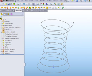
Now lets go back and create the same helix a different way.
1. Let just create a revolved surface 3" high and the radius is 1"
2. Now we need create a helix revolved surface which will fully contact our first revolve. This can be created by a swept surface. Be sure to sketch your path and profile long enough to insure full contact between the two surfaces.


3. Now comes the fun part! use the intersection curve command (Tools, Sketch Tools, Intersection Curve)  and select the two surfaces. You will see a 3D sketch as a result.
 and select the two surfaces. You will see a 3D sketch as a result.

4. Now hide both surfaces.

Why go through all this trouble?? because we can now edit the first revolved surface to any contour we want and create a variable diameter helix!


Hmm...kinda looks like a bed spring??
10/19/2010
Unequally Disposed Profile Tolerance in Solidworks
The new ASME 2009 gives us the option to communicate a profile tolerance that can have an unequal value. This is communicated with "U" in a circle. For definition and information, please refer to para 8.3.1.2, and figures 3-11 and 8.1-8.3 in the ASME Y14.5 2009 standard (see below).


Solidworks 2011 will have this function available, but for those who are using an earlier version will need to do a little work around.
First we will need to edit a dimension or create a dimension we can delete later. In the dimension text editor navigate to the "more" button and select the circle alpha flag not "U". The editor will populate a code snippet . Copy (ctl c) that code. Navigate to the GD&T function and choose the profile symbol, insert (ctl-v) the code into the tolerance area of the feature control frame properties. It helps to put a space before and after the tolerance values. That's it!


Subscribe to:
Comments (Atom)