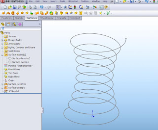
1. Create a circle to drive the diameter of your curve
2. Open the Curve tool and choose the helix command (insert, curve, helix/spiral) Solidworks will automatically pick the open sketch, if is a circle.
3. Now we can choose how to control the helix.
-Pitch and Revolution
- Height and Revolution
- Height and Pitch
- Spiral (defined by pitch and revolution)
The helix's pitch can also be controlled with a constant, which I recommend, or a variable via a mini table. and finally clockwise or counter clockwise.
Now lets go back and create the same helix a different way.
1. Let just create a revolved surface 3" high and the radius is 1"
2. Now we need create a helix revolved surface which will fully contact our first revolve. This can be created by a swept surface. Be sure to sketch your path and profile long enough to insure full contact between the two surfaces.
3. Now comes the fun part! use the intersection curve command (Tools, Sketch Tools, Intersection Curve)  and select the two surfaces. You will see a 3D sketch as a result.
 and select the two surfaces. You will see a 3D sketch as a result.
4. Now hide both surfaces.
Why go through all this trouble?? because we can now edit the first revolved surface to any contour we want and create a variable diameter helix!
Hmm...kinda looks like a bed spring??


1 comment:
What is the scientific name for the material esterlam and is it in Solidworks?
Solidworks Price
Post a Comment